
The Motia Calamp tracking unit is a standard 3 wire installation with fused VCC+ and ignition/switched live connectors.
The MotiaCalamp unit has 2 auxiliary ports that can be used to connect to expansion devices such as the Motia Connect Squarell unit for CAN-Bus tracking data. The Motia Calamp also has several fly leads that can be used for input and/or output triggers to other devices.
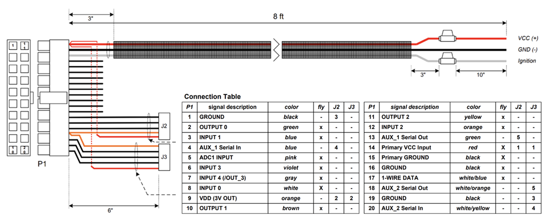
Excluding the 3 wire installation, the primary connectors used by Motia Calamp’s are:
- Aux 2 (J3 Connector on Calamp) to connect to the Motia Connect Squarell Unit
- LTA (Left Turn Alarm) Mute – Output 0 (green fly lead on Motia Calamp)
- DVR Relay – Output 1 (brown fly lead on Motia Calamp)
- Squarell DAP (Driver Assistance Panel) On/Off – Output 2 (yellow fly lead on MotiaCalamp)
***Please read further down this document for instructions on how to make the above connections***
Example images are below of what the Motia Calamp unit looks like and expected installation standard. The Motia Calamp units have many notches around the outer chassis designed for cable ties to firmly secure them to the vehicle’s chassis. This is very important to securely fit the unit so that the accelerometer within the unit performs correctly.
Please install the unit in a discreet location and ensure that adequate GSM (mobile) & GPS (location) connectivity. A solid orange (GSM) and green (GPS) light will indicate the unit is powered and connected to both services.
Motia Calamp Harness Diagram
For further assistance please contact the Motia Support Team on fleetsupport@motia.com or 02894 485 423
**Please find a link below to download the pdf version of this article ***
Comments
0 comments
Article is closed for comments.